

Drive area guide
Drive areas around conveyors work better when the access paths, guarding positions and tool reach are mapped out early for the people who will actually service those drives.
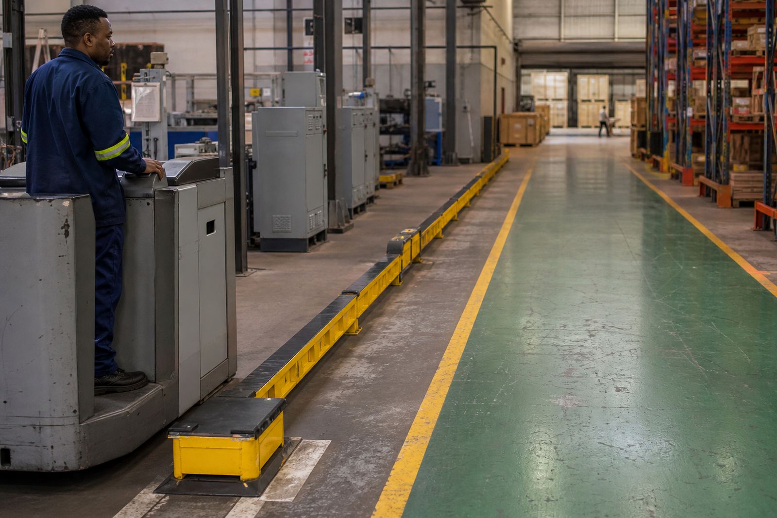
Motor and gearbox zone
Technicians working around each motor and gearbox need enough standing room, reach for tools and clearance for lifting gear so tasks like tensioning, alignment and change‑outs can be done without shifting nearby equipment.
Coupling‑to‑pulley runs on your line work best when belt pull, guard swing, spanner reach and firm standing space are planned at every drive position on the plant. As lubrication points, alignment checks and lockout hardware start to share the same strip of concrete around the drive, what looked generous on a layout drawing can close up and feel crowded.
When a drive is replaced on your plant, mark the installed motor frame, base and guard type directly on the nearby steelwork or guard, together with the running direction. A simple arrow or label showing the service side, anchor locations and cable entry route helps the next team position the new unit correctly, even when the terminal box on a replacement motor ends up on a different face.
Tasks inside the drive area
Teams working at each drive position on your line benefit from clear standing spots, obvious guard release points and open reach to the components that are serviced regularly. Any strip of floor needed for hoists, bearing pullers or coupling alignment tools can be marked so shutdown work and daily running do not compete for the same space around the drive.
Guard fixing points, drain paths and cable routes can be confirmed only once the actual hardware is bolted up and tensioned. Layout changes agreed between production and maintenance at that stage help the installed equipment avoid clashes with chutes, walkways and lifting gear during future interventions.
Checks around each drive position can include:
- Service side marked at the drive
- Guard clearance compared against the mechanical drawing before restart
- Drive reference shown on the motor, guard and nearby steelwork
Conditions around plant drives
Airborne dust from nearby processes settles on cooling fins and terminal boxes, while overspray or steam slowly attacks fasteners, guards and exposed shafts. Legacy plinths and steelwork left from previous machinery can limit how far a drive position can be opened up when production cannot allow a complete strip out.
Wet process zones around the drive call for thought on drainage falls, slip resistance and isolation points that stay reachable during a washdown. In wet process areas, the spacing around the drive also has to leave room for hoses, brushes and removable drip trays to be handled without fighting with the rotating parts.
Planning details for the drive area
Motor size, transmission type and the fault or obstruction at the drive area give a practical starting point for any change. A written description that covers both the working side and the nearest fixed obstruction makes it easier for others to see what can and cannot move in that corner of the plant.
Belt, chain, direct coupling or gearbox layouts should be described clearly, along with any guard that needs to hinge, slide or lift away. Each option changes the support steelwork, mounting positions and how directly hands and tools can reach the drive components during a shutdown.
What our Plant Equipment customers say
Verified Google reviews
Crowded around a drive?
Tell us the motor size, the transmission type and the nearest fixed obstruction.
Start an enquiry